| Switch
spanning
tree algorithm monitor
Overview
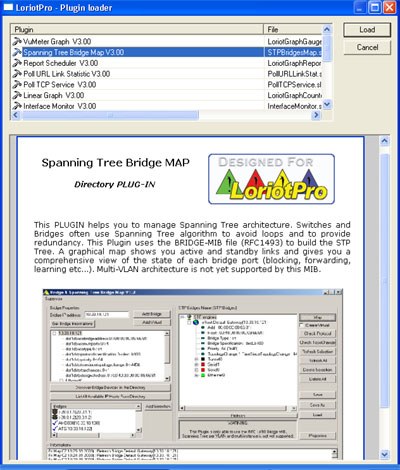
The goal of this LoriotPro Plugin is to monitor bridges and switches
running the Spanning Tree Algorithm. This algorithm is used to determine
when multiple paths exist between two nodes which one should be
active and which one should be in standby. This is necessary to
avoid loop and broadcast packet storm.
Furthermore, the use of a dynamic protocol allows the network administrator
to define backup path and thus improve network availability. Below
two examples of Spanning Tree.
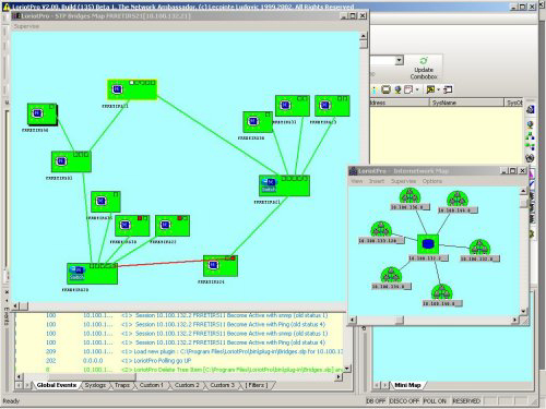
The Plugin through a graphical map performs the supervision. On
this map, all devices behaving as bridge are represented. All ports
and their state (blocking forwarding learning) are also represented.
Links (any kind of network) between bridge ports are also displayed.
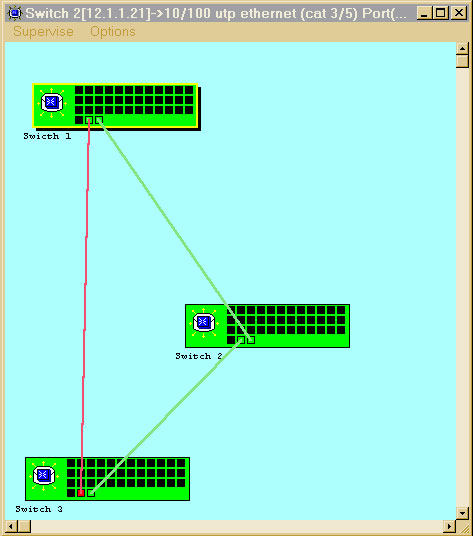
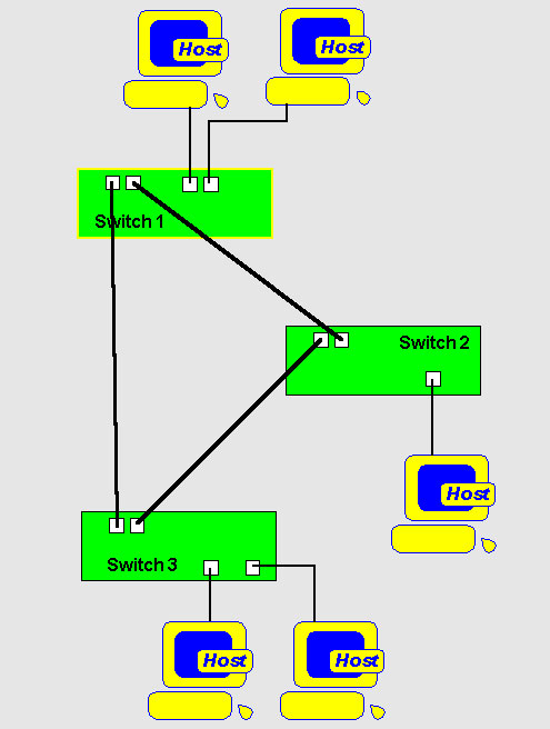
Exemple of a network , Switches are green box, standby link are
in red, active link are in green
The configuration is realized through a visual interface.
Management tasks are performed by direct acces to the Bridge MIB
object
Plugin Installation
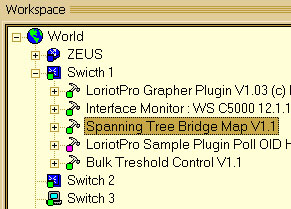
The Plug-In should be attach to one of your host of your Directory.
It could anyway control all the bridge from the same Spanning Tree
domain. Eihter attach it ot one of your switch/bridge or to the
LoriotPro Icon
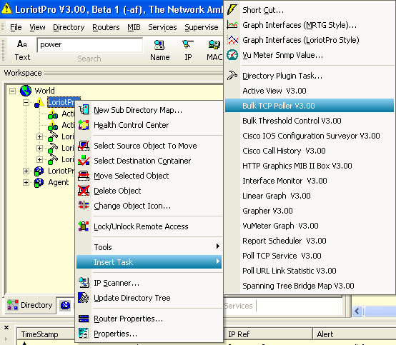
An alternative Way for Plug-in selection is to the Directory
Plug-in task option of the menu which opens a PlugIn
Loader box with explanations on each Plug-in.
Configuration
The configuration of the Bridge Plugin is done from the monitor
Window. To access the monitor Window select the Directory object,
one of your bridge to which the Plugin is attached and double click
on the plugin.
The monitor window opened, you can now proceed to the next step
: add bridges to the list.
You may do that in three ways:
- Manually, if you know the IP address of your Bridges
- Automatically by letting LoriotPro searching the Directory and
discover Bridge devices
- Semi automatically by browsing the directory and picking up
devices
To add a bridge device manually, fill the the Bridge IP Address
field. Press the Add Bridge Button
To let LoriotPro discover the Bridges, press the Discover Bridge
Devices from the Directory Button
To select device from the directory press List All AVailable
Host from the Directory
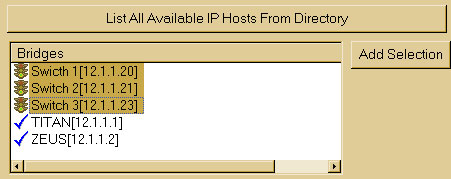
Select the host to add and press Add Selection
The added bridges appears in the right pane of the Window named
STP Instances.
From that point each Bridge in the list will be used by LoriotPro
to create the Map.
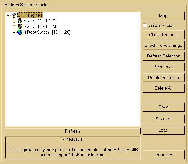
The left buttons of the Pane allows yout to :
| Button Name |
Action |
| Map |
Display the MAP with bridges, links, and current
status |
| Create Virtual |
Create a virtual bridge (bridge known in the Spanning
tree but not manageable by SNMP) |
| Check protocol |
Allows you to check that the Spanning Tree protocol
are from the same type. Result is displayed in the log window
(the bottom pane of this window) |
| CheckTopoChange |
Check the current topology and compare to the
previous state. |
| Refresh Selection |
Refresh the current values for the selected bridge.
(SNMP requests sent to the bridge) |
| Refresh All |
Refresh the current values for all bridges. (SNMP
requests sent to the bridge) |
| Delete Selection |
Delete the selected host from the list |
| Delete All |
Delete All bridges from the List (Of course, they
are not remove from the directory) |
| Save |
Save the current List under the current name |
| Save as |
Save the current list under a new name |
| Load |
Load an previously saved list |
| Properties |
Display the List properties |
| Refresh |
Refresh the screen |
The Properties button open the following window:
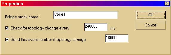
You could specify the Bridge Instance (stack) Name
The interval between each time that LoriotPro will check to see
if the topology has changed.
The alarm number sent to the LoriotPro event manager if the topology
has changed.
The topology change mainly occurs on the following events:
One of the bridge stop to work.
One the link (network) is broken.
You change parameter within the bridge (Path cost, priority, port
status etc...)
A new bridge is added in the network.
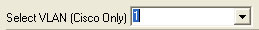
VLAN Selection on CISCO Switch
On Cisco switch only, this Plug-in support Multi-Vlan. To select
the VLAN specify it in the select box:
Review on Spanning
Tree Concepts
To explain the concept of the Spanning Tree we will use a concrete
example.
We defines a network with three Ethernet Switches (working as
multiport Bridge) that are connected together by Ethernet uplinks.
Switches are considered here as Transparent Bridges and support
the RFC1493.
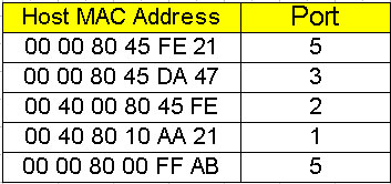
Transparent bridges are so named because their presence and operation
are transparent to network hosts. When transparent bridges are powered
on, they learn the network's topology by analyzing the source address
of incoming frames from all attached networks. In our example, the
switch sees a frame arrive on port 4 from Host A, the switch concludes
that Host A can be reached through the network connected to line
1. Through this process, transparent bridges build a table such
as the one below.
The bridge uses its table as the basis for traffic forwarding.
When a frame is received on one of the bridge's interfaces, the
bridge looks up the frame's destination address in its internal
table. If the table contains an association between the destination
address and any of the bridge's ports aside from the one on which
the frame was received, the frame is forwarded out the indicated
port. If no association is found, the frame is flooded to all ports
except the inbound port. Broadcasts and multicasts are also flooded
in this way.
How the Spanning tree is created ?
The first activity in spanning-tree computation is the selection
of the root bridge (dot1dStpDesignatedRoot),
which is the bridge with the lowest value bridge identifier. In
our example, the root bridge is Switch 1. Next, the root port on
all other bridges is determined. A bridge's root port (dot1dStpRootPort)
is the port through which the root bridge can be reached with the
least aggregate path cost. This value (the least aggregate path
cost to the root) is called the root path cost.
Finally, designated bridges (dot1dStpPortDesignatedBridge)
and their designated ports (dot1dStpPortDesignatedPort)
are determined. A designated bridge is the bridge on each LAN that
provides the minimum root path cost. A LAN's designated bridge is
the only bridge allowed to forward frames to and from the LAN for
which it is the designated bridge. A LAN's designated port is the
port that connects it to the designated bridge.
In some cases, two or more bridges can have the same root path
cost. In this case, the bridge identifiers are used again, this
time to determine the designated bridges.
Cost of a port
To determine the path cost, use this formula:
Interface Path Cost (dot1dStpPortPathCost)
= 1000/Attached LAN speed in Mb/s
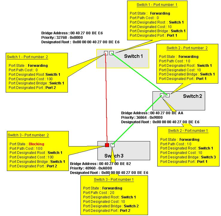
We applied the Spanning Tree Algorithm to our network and we get
the following results. All values are visible from MIB object that
we will detail after.
Supervision
The supervision of the spanning tree is performed directly from
the Bridge Plugin.
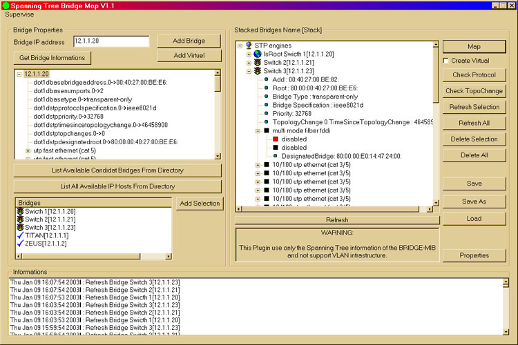
The right pane of the window display all the bridge participating
in the Spanning Tree and from there you could check the current
status of each bridge.
In our example we get the following information for each bridge
Switch 1
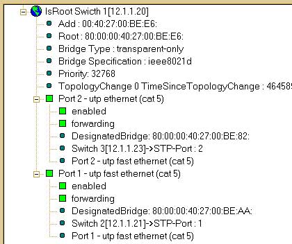
The bridge Switch 1 is root, clearly identified by the earth icon.
We found next the following information :
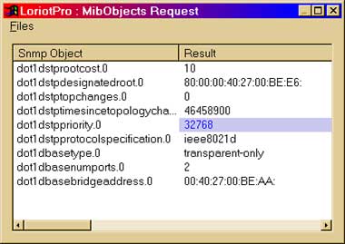
Global parameter for this bridge
The MAC address of the Bridge
The bridge type defined by the MIB Object dot1dBaseType
The Spanning tree version protocol used defined by the MIB object
dot1dStpProtocolSpecification
The Bridge priority defined by the MIB Object dot1dStpPriority.
The value is decimal but it is ofently defined in hexa (here 32768
= 0x8000).
The last time the topologie changed defined by the MIB Object dot1dStpTopChanges
Specific parameter for each port
Port name are identified from the MIB object :
(...mib-2(1).interfaces(2).iftable(2).ifentry(1).ifdescr(2))
The operating status of the port defined by the MIB Object (dot1dStpPortEnable)
The Spanning Tree status defined by the MIB Object (dot1dStpPortState).
The values are 1 disabled, 2 blocking, 3 listenning, 4 learning,
5 forwarding, 6 broken)
The designated bridge for this Lan defined by the MIB Object (dot1dStpPortDesignatedBridge)
The designated port defined by the MIB Object (dot1dStpPortDesignatedPort)Port
name on the designated bridge identified from the MIB object :
(...mib-2(1).interfaces(2).iftable(2).ifentry(1).ifdescr(2))
We get the same information for the two other bridges
Switch 2
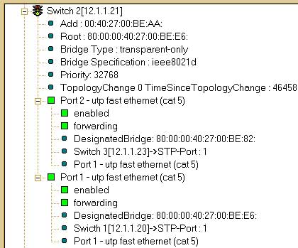
We could see that for the bridge Switch 2 the root Bridge is Swicth
1. The value here is the concatenation of the Priority value 0x8000
(32768) of Switch 1 and its MAC address.
The Switch 2 Port 2 is connected to Switch 3 Port 1.
The Switch 2 Port 2 is connected to Switch 3 Port 1.
Switch 3
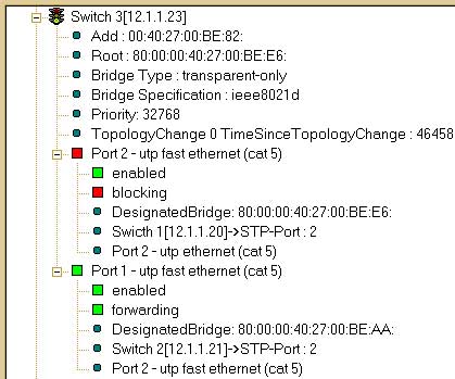
We could see here that the status of the second port of the Switch
3 is Blocking. This is the normal behavior of the Spanning tree,
all the network are available and the best route from Switch 3 to
switch 1 (The root) is by Switch 2. The total cost by this way is
20 against 100 by the direct link.
This is explained here by the link speed between 1-2 and 2-3 which
are Ethernet 100 Mbps against cost 100 the 10 Mbps between 1-3.
On the MAP you could see the same status with color.
The color of the link and port have the following significance
:
|
Color |
Status |
Description |
| |
disabled |
The port is disabled.
|
| |
blocking |
The Spanning Tree algorithm has set this port's
state to "block," meaning that it is enabled but not
passing traffic |
| |
listenning |
The port is in a transitional state, waiting for
the Spanning Tree algorithm to determine whether it should block
or forward traffic |
| |
learning |
The port is learning MAC addresses, but not yet
forwarding traffic
|
| |
forwarding |
The port has been selected by the Spanning Tree
algorithm to forward traffic, and is forwarding traffic currently |
| |
broken |
The port's associated switch port is
blocked, making it impossible for the switch to forward traffic |
Management
The management of the Spanning tree parameters could be done from
the MAP menu. The commands sent from here are SNMP SET and thus
knowing the write community of the bridge agent is necessary to
perform them.
The menu provide the following option:
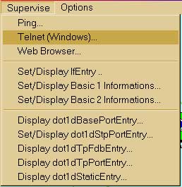
The Menu is divided in three sections:
Tools allow you to do a Ping, Telnet or Browse the MAP selected
Bridge.
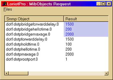
Next three options provides you with informations on the Bridge
Device, list of ports, statistic on the Spanning tree protocol,
STP timer values. Value in purple could be change.
The dot1dStpPriority
could be change here to force a bridge to become root. The Bridge
with the lowest value in a Spanning tree become root. In our exemple
the Swicth 1 has value 0x8000 and is lower than swicth 2 (0x9000)
and switch 3 (0xa000).
The timing value should not be changed or only if your are experimented.
The modification of these values could for example decrease the
convergence (tree reconfiguration).
Anyway, be careful when you change the values here.
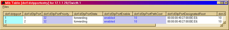
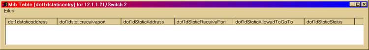
The last five otpions give you Table contains of Spanning Tree
information.
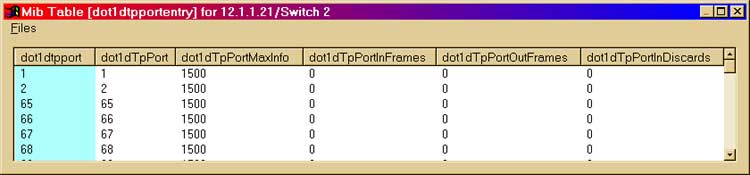
Select a device on the Map and select monitor -> Set/Display
dot1stpPort Entry
To see the significance of each table parameter, refers to the
MIB Object dot1dStpPortEntry
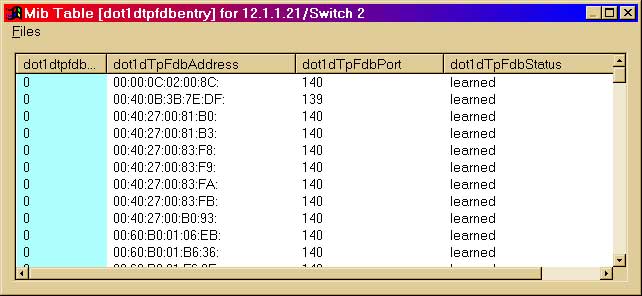
The dot1dTpFdbTable stand for Transparent
Protocol Forwarding DataBase entry and contains for each port of
the Bridge (Switch here) the learned MAC addresses of your hosts.
Restrictions
The Bridge Plugin Support the IEEE 802.1d standard only. If you
use switch and set one STP instance per VLAN you will not be able
to see them except for the Cisco SWITCH.
Spanning Tree Types and switch
| Type |
Meaning |
| IEEE 802.1d |
Each switch is a single 802.1d-compliant bridge. |
| Per VLAN |
Each VLAN functions as a separate 802.1d-compliant
bridge. LoriotPro doesn't support this |
| Disable |
Spanning Tree not used. |
|